Young Surveying Software
A different way to look at points
Entering Points
DXF Import
Controls
Views
COGO Functions
Annotations
Features
TINs - Contours
Laser setup
Home Owner Surveying
What I've learned
System requirements
Free Program Download
Buy
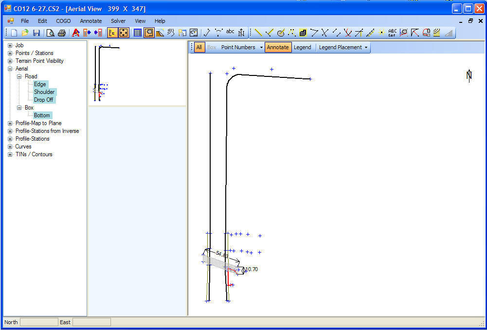
There are four "Views" of the data - Text,
Aerial, Profile
and Contour. The sample below is an
Aerial View showing a North Arrow, dimensioning of points, lines and
curve which represent the edges of a road, and a hatched area which
represents a box culvert.
This program was written in VB2005 and
has the look of Office 2003. The program was designed to turn
things on and off with the minimum of effort -
Point Numbers,
Features,
Annotations, and
Legend are toggled with one click each.
You can easily get the information you need without having to dig thru a
cluttered display. The display redraws and zooms very quickly so "you"
can get the information you need.
Look at the
COGO functions page to see the
visual feedback this program gives
TINs (Triangulated Irregular Network) may be generated
from points - The TIN then can be solved to show
contour lines, the
volume of the TIN above or below a
given elevation, the difference in
volume
between two TINs may be computed, and the
cut / fill between two TINs may be computed
Pictures of below job -
This job information was used in several of the
screen shot examples
Original idea was to buy and set pre-cast box culvert extensions.
These shots let us figure out how big a crane was needed - large
Next idea was pouring extension
Slide area was fixed by fastening a metal culvert to the concrete box then adding fill to
slopes
